

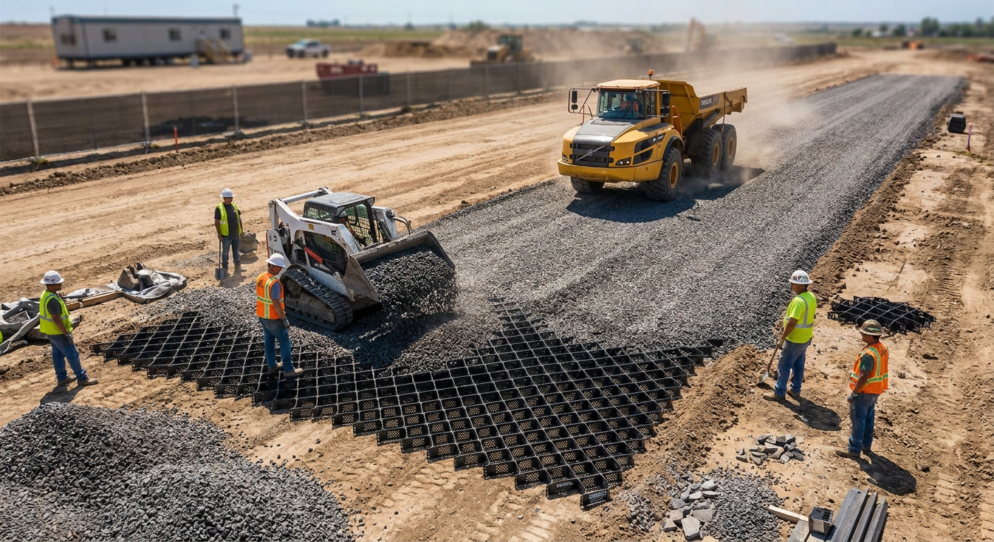
Every construction project begins with the same fundamental challenge: how do you move equipment, materials, and personnel across undeveloped ground without destroying the site, blowing the budget, or creating schedule-killing mud conditions? Temporary construction road design determines whether your site access supports productive operations or becomes a daily battle against rutting, erosion, and equipment damage.
The engineering answer depends on three factors: expected traffic loads (typically H-20 or greater for construction equipment), subgrade bearing capacity (measured in CBR), and project duration. A properly designed temporary road disperses wheel loads through a structural section that prevents subgrade overstress while managing drainage and resisting deformation under repeated loading. BaseCore HD™ Geocell achieves this load dispersion at 4–6 inches of cell depth—reducing aggregate requirements by 40–60% compared to unreinforced designs while delivering H-20+ performance on weak subgrades.
This guide covers the complete engineering methodology for temporary construction road design: load classification, subgrade evaluation, structural section design, drainage integration, and installation best practices. Whether you’re building haul roads for heavy equipment, access roads for delivery trucks, or crane paths for lift operations, the principles here apply across applications.
The Engineering Challenge: Why Temporary Roads Fail
Temporary construction roads operate under conditions that would destroy most permanent pavements. They carry concentrated axle loads from equipment that far exceeds highway traffic—a loaded concrete truck applies 20,000+ pounds per axle, while a crane crawler can exceed 100,000 pounds per track. They do this on subgrades that haven’t been improved, in weather conditions that saturate soils, and with traffic frequencies that compact and degrade aggregate daily.
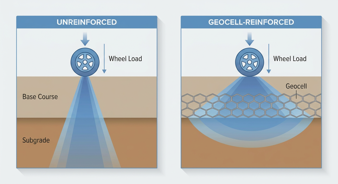
The physics of failure follows predictable patterns. When a wheel load contacts an unconfined aggregate surface, Boussinesq stress distribution concentrates pressure in a cone beneath the contact area. On weak subgrades (CBR below 3), the stress at the subgrade interface exceeds bearing capacity, causing plastic deformation. Each subsequent load cycle compounds the damage through a mechanism called progressive shear failure—aggregate particles displace laterally, rutting deepens, and the road surface loses grade.
The conventional engineering response is aggregate depth: add enough crushed stone to spread the load cone wide enough that subgrade stress stays within bearing limits. The U.S. Army Corps of Engineers’ traditional design methodology calculates required aggregate thickness based on CBR, expected traffic (measured in equivalent single-axle loads), and acceptable rut depth. On a CBR 3 subgrade with 10,000 ESAL traffic, this approach can require 18–24 inches of well-graded aggregate—a specification that makes temporary roads economically impractical on many sites.
The alternative is to change the stress distribution geometry itself. This is where geocell technology transforms temporary road design.
Subgrade Conditions That Drive Design Decisions
Subgrade bearing capacity is the single most important variable in temporary road design. California Bearing Ratio (CBR) testing quantifies this capacity on a scale where well-compacted aggregate scores 80–100 and saturated clay might register below 2. Most construction sites present CBR values between 2 and 8—the range where design decisions have the greatest cost impact.
Soil classification provides the first indicator. USDA and USCS classification systems categorize soils by particle size distribution and plasticity. Sandy and gravelly soils (GW, GP, SW, SP classifications) typically deliver CBR values of 10–40 and drain quickly after rain. Silty soils (ML, MH) range from 5–15 CBR but lose strength rapidly when saturated. Clay soils (CL, CH) present the greatest challenge—CBR values of 2–6 when wet, high plasticity that causes pumping under repeated loads, and poor drainage that prolongs weak conditions.
Groundwater and drainage compound subgrade challenges. A CBR 8 clay that performs adequately in dry conditions might drop to CBR 2 after a week of rain. Temporary road design must account for worst-case moisture conditions, not optimistic assumptions about weather windows.
Load Classification: What Your Equipment Actually Demands
AASHTO load classifications provide the standard framework for structural design. H-20 loading—the baseline for highway design—represents a 20-ton vehicle with an 8,000-pound front axle and 32,000-pound rear axle. Most construction site traffic exceeds this:
- Concrete trucks (loaded): 66,000–80,000 lbs gross, 20,000+ lbs per axle—equivalent to H-20 to HS-20
- Dump trucks (loaded): 50,000–80,000 lbs gross depending on configuration
- Excavators (on transport): 60,000–120,000 lbs gross for mid-size to large equipment
- Mobile cranes: 80,000–200,000+ lbs gross with concentrated outrigger loads
- Tracked equipment: Ground pressure varies from 6–15 psi depending on track width and equipment weight
The design challenge isn’t just maximum load—it’s load frequency and distribution. A road that handles 100 concrete truck passes might fail under 1,000. Traffic analysis must account for construction phasing: foundation pours generate different traffic patterns than steel erection or finish trades.
How Geocell Technology Changes the Engineering Equation
Cellular confinement systems—commonly called geocells—fundamentally alter the load transfer mechanics that govern temporary road design. Understanding these mechanisms explains why BaseCore™ Geocell reduces aggregate requirements while improving performance.
Mechanism 1: Cellular Confinement
HDPE cell walls physically constrain infill aggregate, preventing the lateral displacement that initiates progressive failure. When a wheel load compresses aggregate within a geocell, horizontal pressure builds against the cell walls instead of pushing particles outward. This confinement dramatically increases the apparent stiffness and shear strength of the infill material—transforming loose aggregate into a semi-rigid structural layer.
The confinement effect is quantifiable. Research published in Geotextiles and Geomembranes documents that geocell-reinforced aggregate exhibits 2–3 times the stiffness of unreinforced aggregate at equivalent depths. This increased stiffness means smaller vertical deflections under load, which translates directly to reduced subgrade stress and longer service life.
Mechanism 2: Beam Action
Interconnected geocell panels distribute point loads laterally across adjacent cells. Instead of the Boussinesq cone concentrating stress directly beneath the wheel, load transfers through the geocell structure to engage a wider area of the subgrade. The load dispersion angle improves from the typical 26.5° (for unreinforced aggregate) to 45° or greater with geocell reinforcement.
This wider distribution reduces peak subgrade stress proportionally. A 20,000-pound wheel load that would overstress a CBR 3 subgrade through 6 inches of unreinforced aggregate stays within bearing limits when the same 6 inches incorporates geocell confinement.
Mechanism 3: Membrane Effect
Under vertical loading, the HDPE cell walls develop tensile stress as they resist deformation. This tensioned membrane adds structural capacity beyond what the infill aggregate alone provides. The membrane effect becomes increasingly significant as loads approach the design limit—the geocell structure mobilizes additional resistance precisely when it’s most needed.
These three mechanisms combine to deliver what AASHTO pavement design methodology quantifies as a structural coefficient. BaseCore HD™ Geocell achieves a structural coefficient of 0.35—meaning each inch of geocell-reinforced aggregate provides structural capacity equivalent to 0.35 inches of asphalt concrete. This allows engineers to design thinner sections that meet the same performance requirements as much deeper unreinforced aggregate.
BaseCore’s engineering team provides free project evaluations for temporary road applications. Submit your site conditions and traffic requirements for a geocell depth recommendation specific to your project. Request a quote at basecore.co or call 888-511-1553.
Designing the Structural Section: Step-by-Step Methodology
Temporary road design follows a systematic process that translates site conditions and traffic requirements into a constructible specification. This methodology applies whether you’re designing with geocell reinforcement or conventional aggregate depth.
Step 1: Characterize the Subgrade
Obtain CBR data for the actual subgrade conditions. For preliminary design, soil classification and moisture conditions provide reasonable estimates:
- CBR 1–2: Saturated clay, organic soils, standing water conditions
- CBR 2–4: Wet clay, silty clay, poorly drained fine-grained soils
- CBR 4–6: Moist clay, silty soils with moderate drainage
- CBR 6–10: Sandy silts, clayey sands, soils with reasonable drainage
- CBR 10+: Sandy and gravelly soils, well-drained conditions
Design to the weakest expected condition. If your site includes clay areas that will be saturated during construction, design for CBR 2–3 even if dry-season testing shows CBR 6.
Step 2: Define the Design Traffic
Identify the heaviest equipment that will use the road and estimate total passes over the project duration. Convert this to equivalent single-axle loads (ESALs) using standard conversion factors:
- Passenger vehicles: 0.0002 ESALs per pass
- Single-unit trucks (delivery vehicles): 0.2–0.5 ESALs per pass
- Concrete trucks (loaded): 1.5–2.5 ESALs per pass
- Loaded dump trucks: 1.0–2.0 ESALs per pass
- Heavy construction equipment on transport: 2.0–5.0 ESALs per pass
A typical commercial construction site might accumulate 5,000–20,000 ESALs during the construction phase. Heavy civil projects with continuous haul operations can exceed 100,000 ESALs.
Step 3: Select the Structural System
This decision determines material quantities, installation time, and total installed cost. The options include:
Unreinforced aggregate: Traditional approach using well-graded crushed stone. On weak subgrades (CBR 2–4) with moderate traffic, expect aggregate depths of 12–24 inches. Material and trucking costs scale linearly with depth.
Geotextile separation + aggregate: Adding a geotextile separation layer prevents aggregate contamination by fine-grained subgrade soils, maintaining structural capacity over time. Typical aggregate depth reduction: 10–20% versus unreinforced.
Geogrid-reinforced aggregate: BaseGrid™ Geogrids provide tensile reinforcement at the subgrade interface, reducing required aggregate depth by 20–30% on suitable subgrades.
Geocell-reinforced aggregate: BaseCore HD™ Geocell delivers the most significant depth reduction—40–60% less aggregate than unreinforced designs—while providing the highest load capacity for heavy construction traffic.
Step 4: Calculate Required Depth
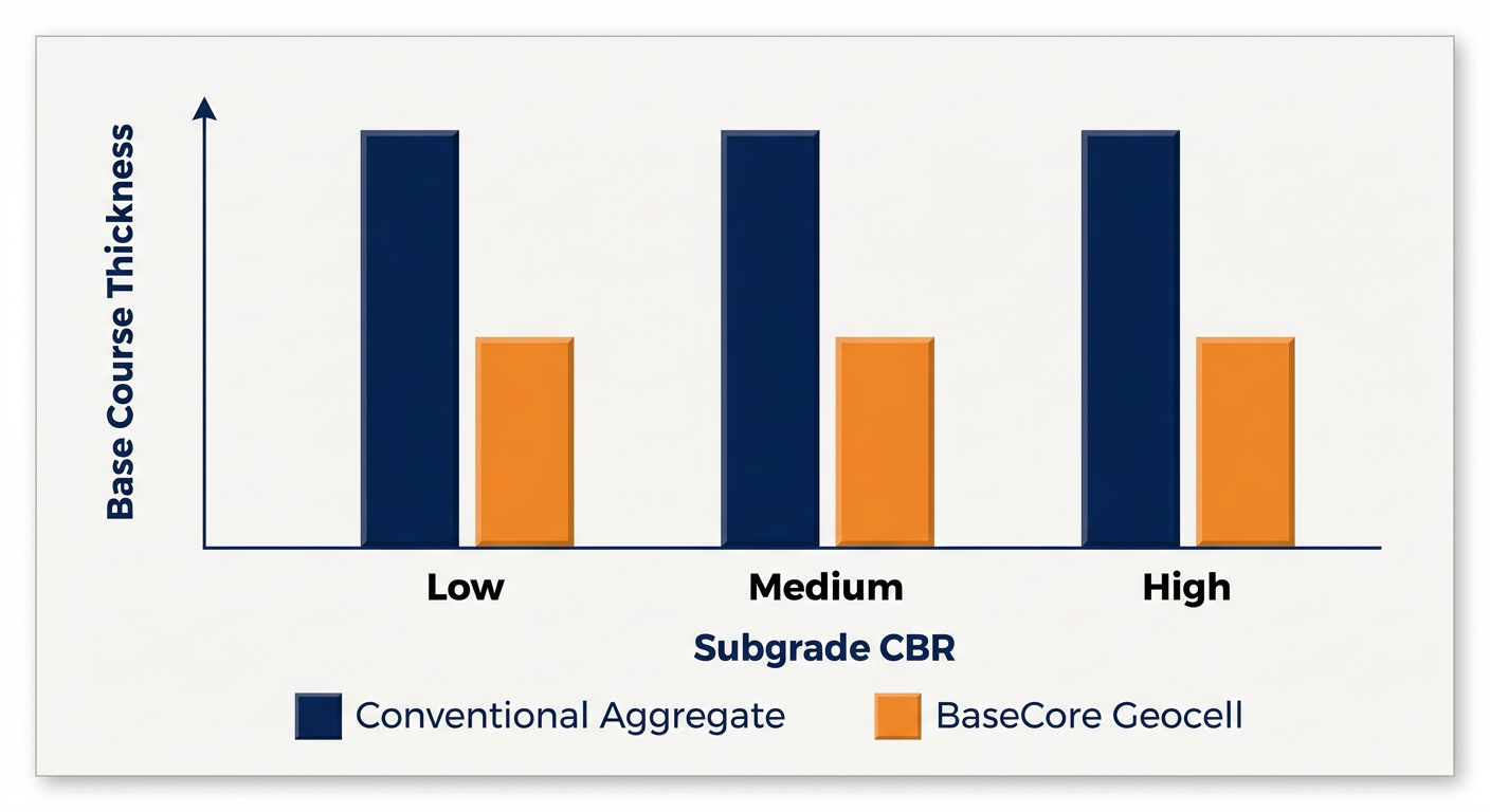
For geocell-reinforced temporary roads, depth selection follows this framework based on subgrade CBR and design traffic:
BaseCore HD™ (8-inch cell depth):
- CBR 2–3: Supports H-20+ loading with 4–6 inches of compacted aggregate infill
- CBR 4–6: Supports HS-20+ loading with 4–6 inches of compacted aggregate infill
- CBR 6+: Supports heavy construction traffic with standard infill
BaseCore™ Standard (4-inch and 6-inch cell depths):
- Light-duty access roads, pedestrian traffic, and equipment staging areas
- Erosion control combined with light vehicle access
- Temporary parking for passenger vehicles and light trucks
The geocell depth versus load capacity relationship is documented in detail in BaseCore’s engineering resources.
Step 5: Specify Infill Material
Infill selection affects both structural performance and constructability. The best geocell infill materials for temporary road applications include:
- Crushed aggregate (3/4″ minus): Optimal balance of compaction, drainage, and structural capacity. Angular particles interlock within cells for maximum confinement benefit.
- Recycled concrete aggregate: Cost-effective alternative with comparable structural performance. Verify gradation and contamination levels.
- Native granular material: Site-sourced sandy gravel can work if gradation is suitable, reducing trucking costs significantly.
- Clean sand: Acceptable for lighter-duty applications but requires verification of drainage and stability under expected loads.
Avoid using fine-grained soils (silt, clay) as primary infill—they lack the interlock and drainage properties that geocell reinforcement requires to perform.
Drainage Integration: The Overlooked Design Element
Water destroys temporary roads faster than traffic. Even a well-designed structural section fails when saturated subgrade loses bearing capacity or surface water erodes the aggregate surface. Effective drainage design is non-negotiable.
Surface Drainage
Crown the road surface to shed water to both sides—typically 2–4% cross-slope depending on traffic speed and surface material. Maintain positive drainage away from the road edge with swales or ditches sized to handle expected runoff. On sloped alignments, install cross-drains or water bars at intervals that prevent erosive flow velocities.
Subsurface Drainage
On sites with high water tables or poor-draining subgrades, consider subsurface drainage alongside the road alignment. French drains, edge drains, or geocomposite drains intercept groundwater before it saturates the subgrade beneath the road.
Geocell systems offer an inherent drainage advantage: the open-cell structure and permeable infill allow vertical drainage through the structural section. Unlike asphalt or concrete, which trap water at the subgrade interface, geocell roads can actually improve site drainage conditions. This permeable design approach often simplifies stormwater permitting by reducing impervious area.
Erosion Protection at Transitions
Where temporary roads cross drainage features, transition from road grades, or connect to permanent improvements, erosion control measures protect the investment. Geocell-lined swales, riprap aprons, and vegetated buffers prevent the concentrated flow that causes head-cutting and road edge failure.
Installation Best Practices for Temporary Roads
Geocell installation follows a straightforward sequence, but attention to detail determines performance. The complete geocell installation guide provides step-by-step procedures; these are the critical points for temporary road applications.
Site Preparation
Clear vegetation and organic material from the road alignment. Grade the subgrade to design profile and cross-slope—don’t rely on the geocell layer to correct grade issues. Compact the subgrade to 95% of maximum dry density where practical; on weak soils, compaction may not be feasible, but remove any loose or disturbed material.
Install geotextile separation fabric if the subgrade contains fine-grained soils that could migrate into the aggregate layer. The geotextile prevents contamination while allowing drainage—a critical combination for long-term performance.
Geocell Deployment
Expand geocell panels to full dimensions and stake in place using the manufacturer’s specified anchoring pattern. Overlap adjacent panels by one cell row and connect with the provided connectors or hog rings. On curves, use pie-cuts or manufactured corner panels to maintain cell geometry.
For temporary roads, anchoring requirements are typically less stringent than permanent installations—the infill weight and traffic compaction provide sufficient stability. However, stake the leading edge and any areas subject to equipment tracking during infill operations.
Infill and Compaction
Fill cells with aggregate in 4-inch lifts, compacting each lift before adding the next. Overfill cells by 1–2 inches to account for compaction settlement. Use vibratory plate compactors for best results; smooth-drum rollers work but may require more passes.
The goal is 95% relative compaction within the cells—the same density standard as conventional aggregate base. Underfilling or undercompacting produces a spongy surface that accelerates wear and reduces load capacity.
Surface Finishing
After final compaction, verify cross-slope and profile grade. Apply a light aggregate topping (1/2″ to 3/4″ crushed stone) to fill any remaining voids and provide a smooth running surface. This wearing course takes the direct abrasion from tire traffic, protecting the structural geocell layer beneath.
Cost Analysis: Geocell vs. Conventional Aggregate Roads
Total installed cost—not material cost per unit—drives temporary road economics. Geocell systems reduce aggregate volume by 40–60%, which translates to savings in material purchase, trucking, and placement labor. On remote sites or projects with limited aggregate sources, these savings often exceed the geocell material cost.
Consider a 1,000-foot temporary haul road, 20 feet wide, on CBR 3 subgrade designed for concrete truck traffic:
Conventional aggregate design: 18 inches of crushed aggregate = 1,111 cubic yards, plus trucking, spreading, and compaction. Material cost varies by region but typically runs $25–45 per cubic yard delivered and placed.
Geocell-reinforced design: 6 inches of BaseCore HD™ with aggregate infill = 370 cubic yards of aggregate plus geocell material. Aggregate volume reduction: 67%.
The breakeven calculation depends on local aggregate costs and site logistics, but on most projects the geocell system delivers lower total installed cost while providing superior performance. The geocell cost breakdown provides detailed analysis for project-specific comparisons.
Additional value factors include:
- Faster installation: Geocell roads install in hours rather than days, reducing site access delays
- Reduced trucking: Fewer aggregate deliveries mean less site congestion and lower fuel costs
- Reusability: HDPE geocell can be recovered and redeployed on future projects
- Lower maintenance: Confined aggregate resists rutting and potholing that requires ongoing repair
Industry Questions Answered
What aggregate depth do I need for temporary construction roads on weak soil?
On CBR 2–4 subgrades with H-20 or greater traffic, conventional unreinforced aggregate roads require 16–24 inches of well-graded crushed stone. BaseCore HD™ Geocell reduces this to 4–6 inches of cell depth plus aggregate infill—a 60–75% reduction in aggregate volume. The exact depth depends on design traffic, subgrade variability, and project duration. BaseCore’s engineering team provides site-specific recommendations through their free project evaluation service.
How long do temporary geocell roads last under heavy construction traffic?
Properly designed and installed geocell roads routinely serve 2–5 year construction projects with daily heavy equipment traffic and require minimal maintenance. The HDPE geocell material has a documented lifespan exceeding 75 years when protected from UV exposure—the aggregate infill provides this protection in road applications. BaseCore case studies document performance across oil and gas, mining, energy, and commercial construction applications with traffic exceeding 100,000 equivalent single-axle loads.
Can geocell temporary roads be removed and the site restored?
Yes—this is a significant advantage over concrete or asphalt alternatives. Geocell panels can be excavated with the aggregate infill, separated, cleaned, and redeployed on future projects. The subgrade beneath experiences minimal disturbance compared to permanent pavements, simplifying site restoration. This removability also supports projects where future development plans differ from construction-phase requirements, making geocell ideal for builder site access roads that will become landscaped areas.
When to Specify BaseCore HD™ vs. Standard Geocell
Product selection matches application requirements. The distinction is straightforward:
BaseCore HD™ Geocell (8-inch cell depth) is engineered for heavy-duty applications: haul roads, crane pads, equipment staging areas, and any application with H-20 or greater loading. The deeper cells and heavier HDPE construction deliver the structural capacity that heavy construction demands. This is the correct choice for temporary roads carrying concrete trucks, loaded dump trucks, or heavy equipment on transport.
BaseCore™ Standard Geocell (4-inch and 6-inch cell depths) serves light to moderate traffic: access roads for pickup trucks and passenger vehicles, temporary parking, pedestrian paths, and erosion control applications that may see occasional vehicle traffic. It also works well for staging areas with forklift traffic or light delivery vehicles.
When in doubt, select the heavier-duty option. The incremental cost of BaseCore HD™ over standard geocell is minor compared to the cost of road failure during critical construction operations.
Conclusion: Engineering Temporary Roads for Construction Success
Effective temporary construction road design eliminates site access as a constraint on project success. The engineering challenge—dispersing heavy wheel loads through a structural section that protects weak subgrades—has a proven solution in geocell technology. By confining aggregate within HDPE cells, improving load distribution angles, and adding membrane tensile capacity, BaseCore HD™ Geocell delivers H-20+ performance at fraction of the aggregate depth conventional designs require.
The result is temporary roads that install faster, cost less, perform better under heavy traffic, and can be removed when construction completes. For civil engineers, general contractors, and site managers facing the universal challenge of reliable site access, geocell-reinforced design offers a technically superior and economically advantageous approach.
Ready to design your temporary road system? Contact BaseCore’s engineering team for a free project evaluation with geocell depth recommendations based on your site conditions and traffic requirements. Call 888-511-1553 or visit basecore.co/quick-basecore-quote to get started.
Frequently Asked Questions
What is the minimum aggregate depth for a temporary construction road on clay soil?
On clay subgrades (CBR 2–4), conventional designs require 16–24 inches of aggregate. Geocell reinforcement reduces this to 4–6 inches of BaseCore HD™ cell depth with aggregate infill. The exact specification depends on expected traffic loads—contact BaseCore’s engineering team for site-specific recommendations based on your subgrade CBR data.
How does geocell reduce temporary road construction costs?
Geocell technology reduces aggregate volume by 40–60% compared to unreinforced designs, cutting material purchase and trucking costs significantly. Additional savings come from faster installation (hours vs. days), reduced maintenance under heavy traffic, and the ability to recover and redeploy geocell panels on future projects.
Can temporary geocell roads handle concrete truck traffic?
Yes. BaseCore HD™ Geocell is engineered for H-20 and HS-20 loading—the classification that covers loaded concrete trucks (66,000–80,000 lbs gross weight). At 4–6 inches of cell depth on CBR 3+ subgrades, BaseCore HD provides the structural capacity for daily concrete delivery traffic throughout multi-year construction projects.
Do temporary geocell roads require maintenance during construction?
Properly installed geocell roads require minimal maintenance compared to unreinforced aggregate roads. The cellular confinement prevents rutting and potholing that typically demands ongoing repair. Periodic inspection, surface grading to maintain crown, and spot topping of aggregate in high-wear areas are typically sufficient for multi-year service.
What permits are needed for temporary construction road installation?
Permit requirements vary by jurisdiction and may include grading permits, stormwater management plans, and erosion control permits. Geocell roads often simplify permitting because their permeable design reduces impervious area calculations and associated stormwater detention requirements. Consult local regulations and your project civil engineer for site-specific permit requirements.
This article is for informational purposes only and does not constitute engineering advice. The technical information provided reflects published geotechnical principles, industry standards, and BaseCore’s product documentation. Site conditions, loading requirements, environmental factors, and regulatory requirements vary by project—consult BaseCore’s engineering team or a licensed professional engineer for project-specific design recommendations. For current product specifications, project evaluations, and pricing, visit basecore.co or call 888-511-1553.