Every driveway, parking lot, haul road, airstrip, crane pad, and construction access surface succeeds or fails on one engineering question: can the soil beneath it carry the concentrated loads applied to its surface without unacceptable deformation? That question is load distribution in soil, and it sits at the foundation of geotechnical engineering, pavement design, and ground stabilization. This guide explains what load distribution in soil actually is, how it works mechanically, how industry-standard geocell depth conventions are set, and why BaseCore HD can deliver the same or better performance at less cell depth — a material, labor, and excavation advantage that compounds on larger projects.
What Is Load Distribution in Soil?

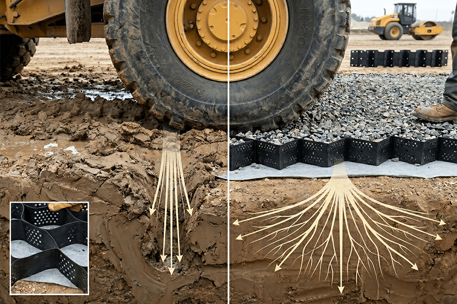
Load distribution in soil is the way a surface load — a wheel, a footing, or any concentrated weight — spreads laterally and downward through layers of aggregate and soil so that pressure on any individual layer stays below that layer’s bearing capacity. Contact pressure at the surface is high and concentrated; bearing pressure at depth is lower and distributed. The layers in between do the structural work of spreading the load.
This is why a loaded 30,000 lb dump truck can drive across a properly engineered gravel road without rutting it, but the same truck sinks into undisturbed bare clay. Both surfaces see identical contact pressure at the tire. The difference is entirely in how each surface redistributes that pressure downward.
Why Does Load Distribution Matter for Pavement and Ground Engineering?
Every load-bearing surface built on soil — pavements, foundations, airstrips, parking lots, haul roads — depends on load distribution to prevent subgrade failure. Adequate distribution produces decades of service life. Inadequate distribution produces rutting, subgrade pumping, bearing capacity failure, and consolidation settlement. Every one of those failures traces back to bearing pressure on the subgrade exceeding its capacity — a load distribution problem.
Specifying a ground reinforcement system is therefore specifying a load-distribution solution. Aggregate thickness, geotextile fabric, and geocell cell depth are all inputs into the same calculation: keep bearing pressure on the subgrade below its allowable limit.
How Does Load Actually Spread Through Soil?

A concentrated surface load spreads through soil following principles first mathematically described by Joseph Boussinesq in 1885. Pressure at any point below the surface depends on depth, distance from the load center, and the stiffness of layers above. In practical pavement engineering, this spreading is often approximated by a load dispersion angle of roughly 30–45 degrees through aggregate layers — every inch of aggregate depth widens the loaded footprint by roughly 0.5 to 1 inch on each side.
The practical consequence: thicker aggregate layers spread loads across a wider subgrade footprint, reducing bearing pressure. Traditional pavement design specifies thicker base courses for heavier loads — more thickness, more spread, lower subgrade pressure. It works but requires a lot of aggregate.
A geocell system changes this equation by widening dispersion and adding load-carrying mechanisms beyond aggregate thickness — which is why BaseCore HD achieves H-20 loading at substantially less depth than unreinforced aggregate would require.
What Are the Three Mechanisms That Distribute Load Through a Geocell?
A geocell distributes load through three mechanisms acting together: cellular confinement, beam action, and membrane action. Each adds load-carrying capacity beyond what aggregate thickness alone delivers. The combination is why a thinner geocell layer can match or exceed the structural performance of substantially thicker unreinforced aggregate.
Mechanism 1: Cellular Confinement
HDPE cell walls contain the infill — crushed stone, sandy soil, asphalt screenings, or milled recycled asphalt — inside rigid boundaries. When load is applied, the infill cannot spread sideways. Confined aggregate behaves mechanically like a much stronger material than the same aggregate unconfined. BaseCore’s published structural coefficient of 0.35 for sandy-soil infill quantifies this: roughly 7 times the coefficient of the same unconfined sandy soil (0.05–0.10).
Mechanism 2: Beam Action
An interconnected geocell mattress behaves like a flexible structural beam. A load at one point transfers through panel connections to adjacent cells, then to their neighbors, spreading outward. Rather than concentrating subgrade pressure directly beneath the tire, the geocell mattress spreads the load across its full footprint.
Mechanism 3: Membrane Action
Under vertical load, the geocell mattress deflects slightly downward and develops tension in the HDPE material itself — similar to how a trampoline tensions under a jumper’s weight. The tensioned geocell redirects some of the vertical load into lateral restraint, further reducing downward pressure reaching the subgrade.
These three mechanisms compound, which is why a 4-inch geocell often outperforms significantly thicker unreinforced aggregate.
What Is the Industry-Standard Geocell Depth Convention?

The geocell industry has developed a fairly consistent depth-to-load convention over decades of specification history. The standard pattern: 2–3 inches for light foot, bike, and trail applications; 3–4 inches for passenger vehicles and light industrial; 4–6 inches for 18-wheelers, oil and gas, mining, and heavy industrial; and 6–8 inches for fire trucks, H-20 loading, and the heaviest applications.
Engineers and specifiers have learned to read competitor specifications against this convention. It is useful shorthand, and BaseCore’s own Selection Guide maps to this range for compatibility and cross-referencing. Here is the standard convention as documented across the industry:
| Application | Industry-Standard Geocell Depth |
| Light foot, trails, bike lanes | 2″–3″ |
| Passenger vehicles, light industrial | 3″–4″ |
| 18-wheelers, oil and gas, mining | 4″–6″ |
| Fire trucks, H-20 loading, heavy industrial | 6″–8″ |
This is the reference point every specifier brings to a geocell discussion.
How Does BaseCore HD Change the Depth Math?
BaseCore HD achieves equivalent load distribution performance at reduced cell depth compared to the industry-standard convention, because the HDPE composition, seam peel strength (1,420–2,000 N per ASTM D6392), and manufacturing quality produce stronger cell walls and more effective load transfer between panels. The practical result is that BaseCore HD supports full H-20 loading at 4–6 inches — the lower end of the industry range — while still matching the heavier-duty industrial specifications at 8 inches when additional drainage or extreme-load tolerance is required.
Here is the BaseCore HD specification against the industry-standard convention:
| Load Category | Industry Convention | BaseCore HD | Advantage |
| Residential driveway, light passenger vehicle | 3″–4″ | 3″ | Minimal depth at industry low end |
| H-20 loading (fire trucks, loaded commercial trucks, emergency access) | 6″–8″ | 4″–6″ | H-20 achieved at 4″, optional 6″ for conservative spec |
| Heavy construction (loaded dump trucks, excavators, staging) | 6″–8″ | 6″ | Heavy construction at industry low end |
| Industrial, crane pads, drainage-intensive applications | 8″+ | 8″ | Matches industry for high-demand applications |
The depth-reduction advantage compounds into four operational benefits: less excavation (shallower dig = less labor, less haul-away spoils), less aggregate (shallower base course = less stone to purchase and transport), faster installation (less material to move = more square feet per day), and lower total installed cost.
On a 50,000 square foot project specifying H-20 loading, moving from a conventional 8-inch cell depth to a 4-inch BaseCore HD cell depth reduces excavation volume by roughly 50%, reduces infill volume by roughly 50%, and typically reduces labor hours correspondingly. The structural performance remains at H-20.
What Is H-20 Loading and Why Does It Matter?
H-20 (technically AASHTO HS-20) is the American Association of State Highway and Transportation Officials design load standard representing a 20-ton (40,000 lb) design truck with rear axle loading of 32,000 lb. H-20 is the governing design load for bridges, culverts, fire lanes, and most heavy commercial pavement design in the United States. When a specification calls for H-20 loading, it means the surface must support fire trucks, loaded commercial trucks, and equivalent heavy vehicles without deformation failure.
H-20 is therefore the threshold most commercial and municipal projects are designed against. A geocell system that meets H-20 at 4 inches delivers the same rated performance as an 8-inch industry-standard geocell — at half the cell depth, half the aggregate depth, and proportionally lower installed cost.
What Is Contact Pressure and Why Does It Matter?
Contact pressure is the force per unit area at the point where a load meets the surface, typically measured in pounds per square inch (psi). A passenger car tire produces 30–35 psi of contact pressure. A loaded dump truck tire produces 80–120 psi. An H-20 design truck loads the pavement at pressures well within this range. A mobile crane outrigger pad can exceed 500 psi. Every load distribution calculation starts with contact pressure because it sets the initial intensity the soil layers below must disperse.
The engineering challenge is straightforward: at the surface, contact pressure is high and concentrated. At the subgrade (8–14 inches below a BaseCore surface), pressure must drop to a value the underlying soil can safely carry. A weak clay subgrade might have an allowable bearing pressure of only 3–5 psi. An 80 psi tire contact pressure must be distributed down by 16–20x before reaching the subgrade, or the soil fails.
Aggregate thickness, confinement, and engineered geocell reinforcement are the tools that accomplish this reduction — and BaseCore HD accomplishes it with less aggregate than unreinforced or lower-grade alternatives.
What Happens When Load Distribution Fails?

When load distribution fails, ground pressure exceeds the soil’s bearing capacity and the soil deforms. Failure progresses through a predictable four-stage sequence: rut initiation under concentrated contact pressure, water accumulation in the rut, subgrade softening from retained moisture, and propagating failure as adjacent soil is loaded beyond capacity.
Stage 1: Rut Initiation
A loaded tire or track applies contact pressure exceeding subgrade ultimate bearing capacity. Soil beneath the contact point deforms downward by fractions of an inch per pass, creating an initial depression.
Stage 2: Water Pooling
The depression collects water from rain or surface runoff. Water reduces soil strength — particularly in clays and silts — through increased pore pressure and reduced effective stress.
Stage 3: Subgrade Softening
Softened subgrade has lower bearing capacity than dry subgrade. Each subsequent pass deforms the soil more easily. The rut deepens faster, accelerating failure.
Stage 4: Progressive Failure
Deep ruts force traffic to track aside, loading previously unstressed soil. Subgrade fines pump upward into the aggregate base, contaminating it. Washouts, potholes, and bare spots propagate across the surface.
This entire sequence is a load distribution problem. A properly specified geocell — at whatever depth the application requires — prevents it by keeping bearing pressure below soil capacity from the beginning.
What Factors Govern Load Distribution Performance?
Several variables determine how effectively any system distributes load into soil.
Layer Thickness
Thicker aggregate and reinforced layers spread loads wider. The relationship is non-linear but meaningful. Reinforced systems like BaseCore HD achieve the same spreading at less thickness than unreinforced alternatives.
Layer Stiffness (Modulus)
Stiffer layers spread load more effectively. BaseCore HD filled with sandy soil at a structural coefficient of 0.35 is approximately 7x stiffer than unconfined sandy soil at 0.05–0.10, measurably improving spreading performance.
Subgrade Bearing Capacity
Soft subgrade requires more spreading above it to avoid overstressing. Stiff subgrade tolerates higher bearing pressures. California Bearing Ratio (CBR) quantifies this capacity.
Load Magnitude and Repetitions
A one-time heavy load and a repeating lighter load produce different outcomes. Repeated loading fatigues aggregate and consolidates subgrade over time, even at pressures below single-load capacity.
Moisture and Drainage
Saturated subgrade has dramatically lower bearing capacity than dry subgrade. Permeable systems maintaining 90%+ permeability — like BaseCore filled with crushed stone — keep subgrade drier than impermeable asphalt or concrete, preserving bearing capacity over the service life.
Contact Pressure
Higher contact pressure demands more distribution. Crane outriggers, piling rigs, and loaded dump trucks drive specification higher.
Where Does Load Distribution Engineering Apply in the Real World?
Pavements
Every asphalt and concrete pavement is designed to distribute vehicle loads from surface to subgrade at pressures below subgrade capacity. Thickness, base depth, and subgrade stiffness are all calculated to that criterion.
Foundations
Shallow footings, mat foundations, and pile caps are load-distribution systems — spreading a column load across a wider soil footprint so bearing pressure stays within limits.
Construction Haul Roads
Temporary construction roads over variable soil require engineered load distribution. See how to reinforce soft soil for construction projects for dedicated guidance.
Parking Lots, Driveways, and Access Roads
Commercial parking, residential driveways, and rural access roads all depend on load distribution to avoid rutting. BaseCore HD typically substitutes for traditional paving in most of these applications.
Crane and Piling Rig Pads
Mobile crane outrigger pads can exceed 500 psi contact pressure. Pad design is fundamentally load distribution — spread outrigger load wide enough that subgrade stays below capacity.
Airstrips and Helipads
Unpaved airstrips and helipads distribute aircraft tire and rotor-generated loads. Geocell reinforcement is widely used for private airstrips, backcountry strips, and helipads.
Railway Ballast Support
Rail ballast transmits locomotive loads to subgrade. Geocell reinforcement of ballast is an established application on high-tonnage lines.
Wind Turbine and Solar Farm Access
Renewable energy projects require long access roads over variable soil. Load distribution engineering sets haul-road and crane-path specification across the site.
How Do You Specify a Load-Distribution System?
Specification starts with quantifying applied load, evaluating subgrade, and selecting a layer system — aggregate thickness, reinforcement type, geotextile fabric — that reduces subgrade bearing pressure below soil capacity. BaseCore HD’s specification efficiency shortens the depth needed at every load category above residential.
| Application | Industry Convention | BaseCore HD Specification |
| Residential driveway | 3″–4″ | 3″ |
| H-20 loading | 6″–8″ | 4″–6″ |
| Heavy construction | 6″–8″ | 6″ |
| Industrial or drainage-intensive | 8″+ | 8″ |
Where the application is unclear or the subgrade is marginal, the BaseCore consultation process reviews site conditions, soil data, and load documentation before finalizing specification. Full professional installation standards are documented in BaseCore’s installation guide.
Conclusion
Load distribution in soil is the engineering principle behind every successful pavement, foundation, parking lot, haul road, airstrip, and construction access surface. Adequate distribution delivers decades of service; inadequate distribution produces the rutting, pumping, and progressive failure that plague unreinforced surfaces. Geocell reinforcement distributes load through three mechanisms — cellular confinement, beam action, and membrane action — that aggregate thickness alone cannot replicate.
The geocell industry has developed a consistent depth-to-load convention, and specifiers reliably map projects against it. BaseCore HD works within that convention but delivers equivalent or better performance at reduced cell depth: H-20 loading at 4–6 inches versus the 6–8 inches commonly specified, residential driveways at 3 inches, heavy construction at 6 inches, and industrial or drainage-intensive applications at 8 inches. The depth-reduction advantage compounds into less excavation, less aggregate, faster installation, and lower total installed cost — while preserving the same structural performance and the 60+ year service life. Request a tailored quote at basecore.co/quick-basecore-quote or call 888-511-1553.
Frequently Asked Questions
What is load distribution in soil in simple terms?
Load distribution in soil is how concentrated weight from a tire or footing spreads outward and downward through ground layers. Properly distributed, pressure at the subgrade stays below soil capacity and the surface performs. Poorly distributed, the soil fails and the surface rutts or collapses.
How does a geocell improve load distribution?
A geocell improves distribution through three mechanisms: cellular confinement (walls prevent infill from spreading), beam action (the interconnected mattress spreads load laterally), and membrane action (geocell tension redirects vertical forces sideways). Combined, these produce roughly 7x higher structural coefficient than unconfined infill.
What BaseCore HD depth do I need for H-20 loading?
BaseCore HD supports H-20 loading at 4–6 inches. This compares to the industry-standard convention of 6–8 inches for H-20 applications. The 4-inch specification is appropriate for most commercial H-20 projects; the 6-inch specification offers a conservative margin for heavily loaded or marginal subgrade sites.
What BaseCore HD depth should I use for a residential driveway?
Use 3 inches of BaseCore HD for residential driveway applications. This depth supports passenger vehicles and light delivery traffic at the low end of the industry convention while delivering the full structural coefficient and 60+ year service life of the HD product line.
What is the advantage of BaseCore HD’s reduced cell depth?
Reduced cell depth means less excavation, less imported aggregate, faster installation, and lower total installed cost — all while maintaining equivalent structural performance. On large projects, moving from 8 inches to 4 inches at H-20 loading can reduce excavation and infill volumes by roughly 50%.
This article references publicly available information from BaseCore (Scottsdale, Arizona), including the BaseCore Submittal Sheet, BaseCore Installation Guide, BaseCore Geocell Selection Guide, BaseCore Weights chart, and structural coefficient data published in the Installation Guide. Technical specifications reference ASTM D5199, D6392, D6818, D6454, D1693, D4355, and AASHTO T-180 standards. H-20 loading references AASHTO HS-20 design load standards. Classical load distribution theory references Boussinesq stress distribution and standard geotechnical engineering practice. External references include U.S. Federal Highway Administration geotechnical and geosynthetic design guidelines. Industry-standard geocell depth conventions are documented across public geocell product literature and geotechnical engineering references. Results described are specific to the applications referenced and may vary based on site conditions, soil type, load specification, and installation technique. For current specifications, pricing, and warranty details, consult basecore.co or call 888-511-1553.