

Every civil engineer specifying geocell technology faces the same fundamental question: what are the critical construction details that determine whether a cellular confinement system delivers its engineered performance—or fails prematurely under load?
Geocell construction details encompass subgrade preparation to minimum 95% Standard Proctor density, panel deployment with HDPE cell walls oriented perpendicular to primary traffic direction, connection of adjacent panels using polymer tendons at 2-cell intervals, infill material selection matching CBR and permeability requirements, and compaction to 95-98% Modified Proctor in controlled lifts not exceeding cell depth. These specifications ensure the three load-carrying mechanisms—cellular confinement, beam action, and membrane effect—function as designed.
This guide provides the complete construction sequence for BaseCore™ Geocell and BaseCore HD™ Geocell systems, covering design parameters, material specifications, installation procedures, connection details, and quality control protocols that specifying engineers and contractors require for commercial, industrial, and infrastructure applications.
The Engineering Foundation: Why Construction Details Determine Geocell Performance
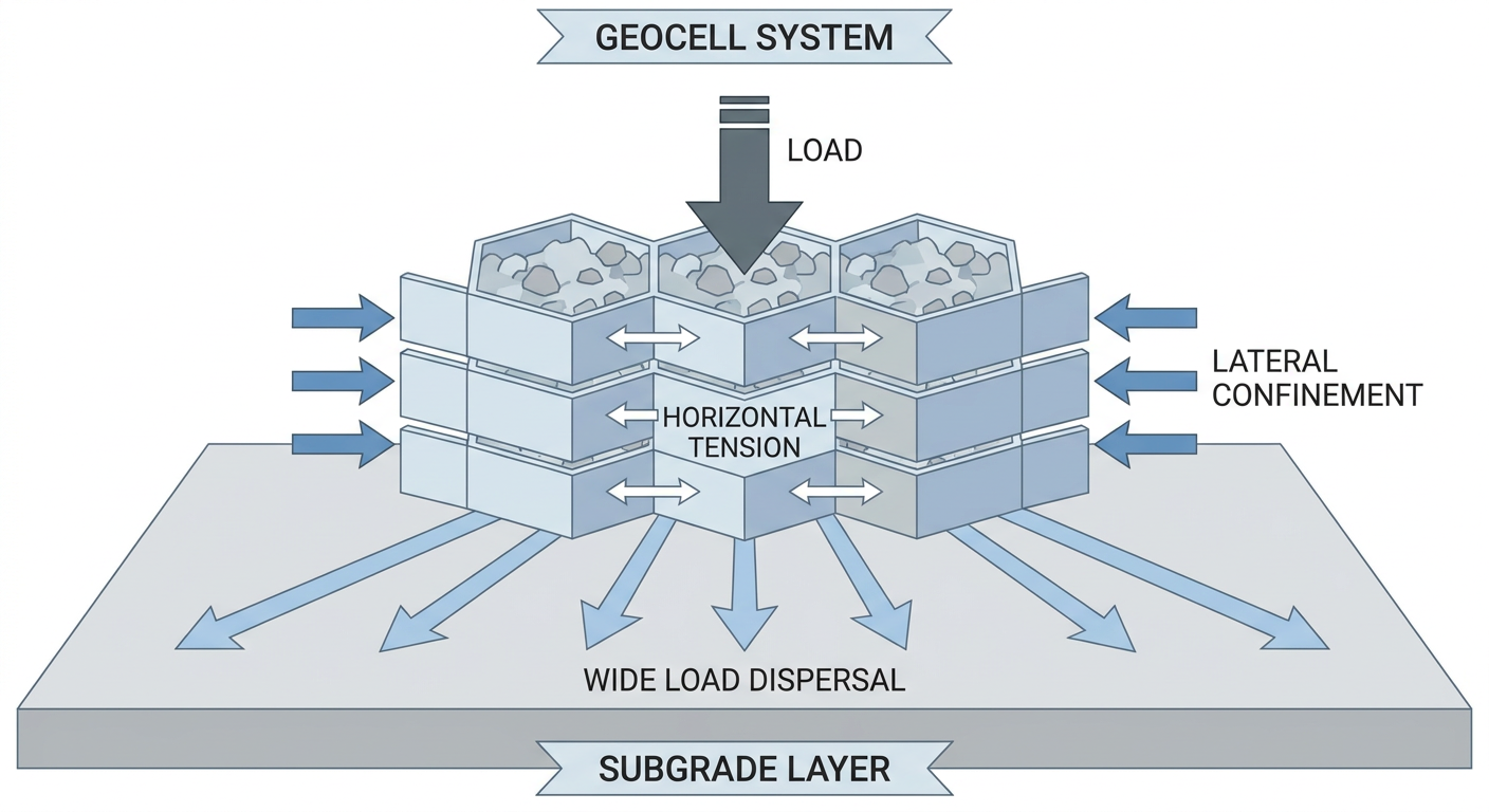
Geocell technology operates through three distinct load-carrying mechanisms, each dependent on proper construction execution. Understanding these mechanisms explains why specific construction details—not just material selection—govern system performance.
Mechanism 1: Cellular Confinement
HDPE cell walls prevent lateral displacement of infill aggregate under vertical loading. When a wheel load or equipment pad applies pressure, unconfined aggregate would normally spread laterally, reducing bearing capacity and creating rutting. The geocell’s three-dimensional cell structure restrains this lateral movement, dramatically increasing the apparent stiffness and load-bearing capacity of the confined material.
Construction implication: Cell walls must maintain structural integrity during installation. Infill placement and compaction procedures that damage cell walls compromise the confinement mechanism. Overfilling cells before compaction or using oversized aggregate that punctures HDPE walls eliminates the engineering advantage.
Mechanism 2: Beam Action
Interconnected geocell panels distribute point loads laterally across adjacent cells, spreading concentrated pressure across a wider subgrade area. This load distribution follows principles similar to Boussinesq stress distribution but with enhanced lateral transfer due to the rigid panel structure.
Construction implication: Panel-to-panel connections must maintain structural continuity. Gaps between panels, missing connection tendons, or improperly tensioned joints create weak points where load transfer fails. The construction detail that determines beam action performance is connection integrity—not just panel material quality.
Mechanism 3: Membrane Effect
Under vertical loading, HDPE cell walls develop tensile forces that redistribute applied loads through the panel structure. This membrane effect adds structural capacity beyond what the infill material alone provides, with the tensioned cell walls acting as a load-transferring network.
Construction implication: Panels must be stretched to proper tension during deployment. Slack panels with wrinkled or folded cell walls cannot develop membrane tension under load. The deployment procedure—specifically the stretching and anchoring sequence—determines whether membrane effect contributes to structural capacity.
The load distribution principles that govern geocell performance require all three mechanisms to function simultaneously. Construction defects that compromise any single mechanism reduce overall system capacity disproportionately to the affected area.
How BaseCore Geocell Systems Address Construction Variables
BaseCore manufactures two geocell product lines engineered for different load classifications and applications. Understanding the construction detail differences between these systems allows specifying engineers to match product selection to project requirements.
BaseCore™ Geocell: Standard Applications
BaseCore™ Geocell delivers structural performance for moderate-load applications including access roads, parking areas, erosion control, and slope protection. The standard product uses HDPE cell walls with sufficient thickness for confined aggregate systems under passenger vehicle traffic, light trucks, and equipment with ground pressures below 25 PSI.
Construction detail specifications for BaseCore™:
- Cell depth options: 2″, 3″, 4″, 6″, 8″ depending on load classification and subgrade CBR
- Cell wall thickness: Engineered for confinement of standard aggregate infill
- Panel dimensions: Expandable honeycomb structure covering large areas efficiently
- Connection method: Polymer tendons through pre-formed apertures at 2-cell intervals
- Minimum subgrade CBR: 3% with geotextile separation; higher CBR subgrades permit reduced cell depth
BaseCore HD™ Geocell: Heavy-Duty Applications
BaseCore HD™ Geocell provides enhanced structural capacity for H-20 and HS-20 load classifications required for road construction, rig pads, crane pads, airport taxiways, and industrial yards handling heavy equipment. The HD product achieves a structural coefficient of 0.35—comparable to hot-mix asphalt—allowing substantial reduction in total pavement section thickness.
Construction detail specifications for BaseCore HD™:
- Cell depth: 4″ to 8″ for H-20 loading depending on subgrade conditions
- Structural coefficient: 0.35 (AASHTO pavement design methodology)
- Load capacity: H-20/HS-20 equivalent single-axle loading
- Connection method: Heavy-duty polymer tendons with increased tensile capacity
- Infill specification: Angular, well-graded aggregate meeting AASHTO M 147 or project specifications
The HD product’s enhanced specifications translate to specific construction requirements: tighter compaction tolerances, more stringent infill gradation control, and connection verification protocols appropriate for structural applications.
BaseCore’s engineering team provides free project evaluations including geocell depth recommendations based on your site’s CBR data and expected loading. Request a quote at basecore.co/quick-basecore-quote or call 888-511-1553.
Construction Sequence: Detailed Procedures for Geocell Installation
Proper geocell construction follows a defined sequence where each phase establishes conditions for subsequent operations. Shortcutting early phases—particularly subgrade preparation—creates compounding problems that manifest as performance failures under service loading.
Phase 1: Subgrade Preparation
Subgrade condition determines the foundation for all subsequent geocell performance. The cellular confinement system enhances the load-bearing capacity of the infill material, but cannot compensate for a subgrade that continues to consolidate, heave, or pump water under repeated loading.
Subgrade preparation requirements:
- Excavation: Remove organic material, topsoil, and unsuitable soils to reach stable native material or engineered fill. Excavation depth depends on load requirements, frost depth (cold climates), and presence of expansive or compressible soils.
- Grading: Establish design grades with cross-slope for drainage (typically 2% minimum for paved surfaces, 1-3% for unpaved access roads). Grade tolerance: ±0.5″ for structural applications, ±1″ for erosion control.
- Compaction: Compact subgrade to minimum 95% Standard Proctor density (ASTM D698). For heavy-duty applications (H-20+), specify 98% Standard Proctor or 95% Modified Proctor (ASTM D1557).
- Proof rolling: Proof roll subgrade with loaded dump truck or roller to identify soft spots requiring remediation. Mark and excavate/replace any areas showing deflection greater than 1″.
- CBR verification: Conduct CBR testing per ASTM D1883 at specified intervals (typically 1 test per 2,500-5,000 SF for structural applications). Document CBR values for geocell depth selection.
Phase 2: Geotextile Separation Layer
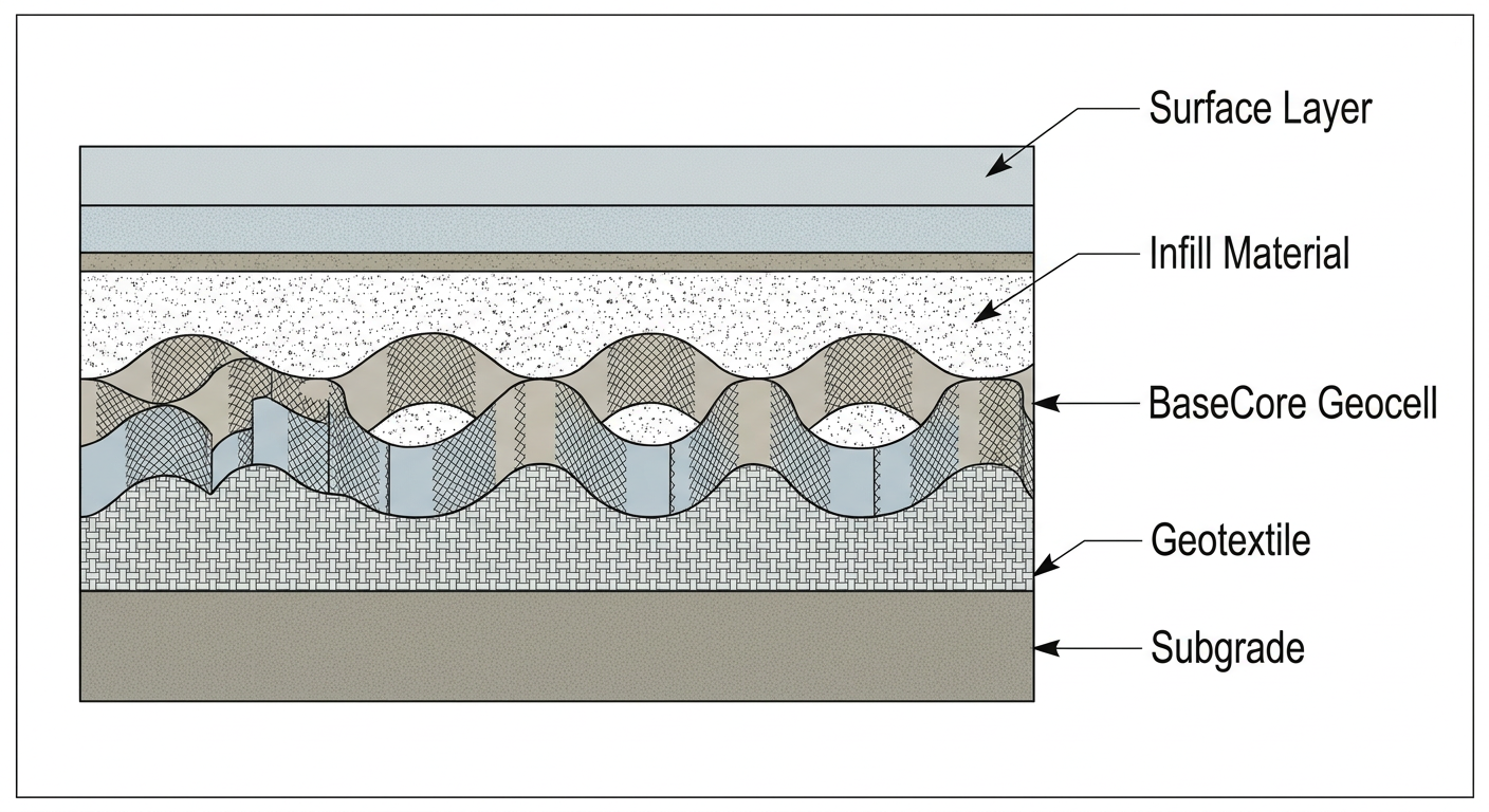
A geotextile separation fabric between subgrade and geocell serves multiple engineering functions: preventing fine-grained subgrade soil from migrating into the aggregate infill (which reduces infill CBR over time), providing filtration for groundwater movement, and adding tensile reinforcement at the subgrade interface.
Geotextile installation requirements:
- Material selection: Non-woven geotextile with minimum grab tensile strength of 200 lbs (ASTM D4632), apparent opening size (AOS) appropriate for subgrade soil type, and permittivity sufficient for site drainage conditions.
- Overlap: Minimum 12″ overlap at all seams for separation function; 18-24″ overlap for filtration-critical applications or on slopes.
- Anchoring: Secure geotextile edges with staples, pins, or backfill to prevent displacement during geocell deployment. In windy conditions, weight fabric with sandbags or aggregate until geocell panels are in place.
- Wrinkle control: Pull fabric taut to eliminate wrinkles that create stress concentrations or interfere with geocell seating.
For weak subgrades (CBR below 3%), consider adding BaseGrid™ Geogrid below the geotextile for additional subgrade reinforcement. This combination addresses the distinct engineering functions of tensile reinforcement (geogrid), separation/filtration (geotextile), and load distribution (geocell).
Phase 3: Geocell Panel Deployment
Geocell panels arrive collapsed and expand to their installed dimensions during deployment. Proper expansion technique and panel orientation directly affect the three load-carrying mechanisms.
Deployment procedure:
- Panel orientation: Position panels with cell walls perpendicular to the primary traffic direction. This orientation maximizes beam action for load distribution across the traffic lane. For parking areas with multi-directional traffic, orient panels perpendicular to the direction of heaviest or most frequent loading.
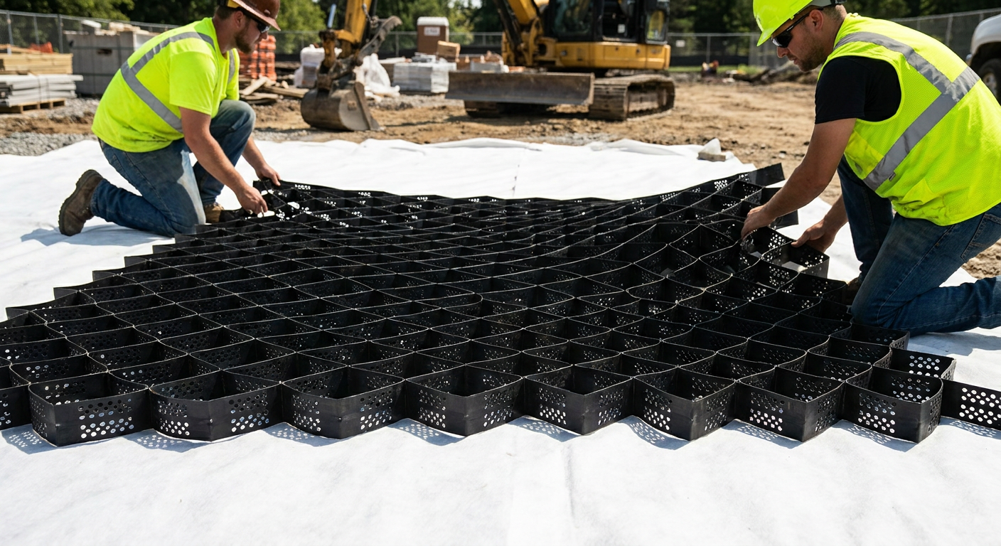
- Expansion: Expand collapsed panel to full design dimensions. For large panels, this typically requires 2-3 workers pulling opposing corners while a third worker guides the panel into position. Do not force expansion—HDPE material should stretch smoothly without kinking.
- Tensioning: Stretch panel to eliminate slack in cell walls. Proper tensioning is achieved when cell walls are taut but not overstressed. Anchor leading edge with J-hooks, stakes, or partial infill before releasing trailing edge.
- Positioning: Align panel edges with adjacent panels for connection. Maintain consistent cell wall orientation across the installation area.
- Edge treatment: At project boundaries, cut cells cleanly with utility knife or saw. For structural applications, anchor edge cells with stakes or embed in concrete edging. For erosion control applications, extend panels into anchor trenches at top of slope.
Phase 4: Panel-to-Panel Connections
Connection integrity determines whether the geocell system functions as a unified structural panel or as disconnected individual cells. Improper connections create planes of weakness where differential settlement, rutting, and edge separation initiate.
Connection specifications:
- Connection hardware: Polymer tendons (included with BaseCore products) thread through pre-formed apertures in adjacent cell walls. Metal fasteners are not recommended—they corrode, create stress concentrations, and can puncture cell walls.
- Connection spacing: Install tendons at 2-cell intervals (every other cell) along the entire panel seam. For heavy-duty applications, reduce to every-cell connection.
- Tensioning: Pull tendons snug to bring adjacent cell walls into contact. Do not over-tension—the goal is contact, not compression that deforms cell walls.
- Verification: After connection, verify that panels cannot separate by applying lateral force at mid-span between connection points. Any separation indicates insufficient connection density or improperly secured tendons.
Detailed geocell installation procedures including connection methods are available in BaseCore’s technical documentation.
Phase 5: Infill Material Placement
Infill material selection and placement directly affect the confined material’s CBR and, consequently, the system’s load-bearing capacity. The geocell provides confinement; the infill provides bearing strength.
Infill material selection criteria:
- Gradation: Well-graded angular aggregate with maximum particle size not exceeding 2/3 of cell depth. For 4″ cells, maximum aggregate size is approximately 2.5″. Fines content (passing #200 sieve) should not exceed 8% for structural applications to maintain permeability and prevent pumping.
- Shape: Angular, crushed aggregate provides higher confined CBR than rounded river gravel. Angular particles interlock within cells, increasing resistance to displacement under load.
- Durability: Aggregate should meet AASHTO M 147 or project specifications for LA abrasion, soundness, and deleterious materials. For industrial applications with heavy equipment, specify aggregate with LA abrasion loss below 40%.
- Local availability: Coordinate with local aggregate suppliers early in project planning. Transportation costs often exceed material costs—local sourcing reduces total installed cost. Review the best geocell infill materials guide for detailed selection criteria.
Placement procedure:
- Initial lift: Place infill in lifts not exceeding cell depth. For 6″ cells, place 6″ maximum loose lift thickness. Do not overfill cells—excess material above cell walls interferes with compaction and creates an unconfined layer.
- Distribution: Spread infill evenly using backhoe, skid steer, or hand tools. Ensure complete cell filling with no voids against cell walls. For large areas, use motor grader or dozer for efficient spreading.
- Avoid cell wall damage: Do not drive tracked equipment directly on empty or partially filled geocell panels. Use rubber-tired equipment or work from completed (filled and compacted) sections.
Phase 6: Compaction
Compaction transforms loose aggregate into a high-density confined structural layer. Under-compaction leaves the system vulnerable to post-construction settlement; over-compaction (rare with proper procedure) can damage cell walls.
Compaction specifications:
- Target density: 95-98% Modified Proctor (ASTM D1557) for structural applications. Erosion control applications may specify 95% Standard Proctor depending on loading requirements.
- Equipment: Vibratory plate compactor (minimum 5,000 lb force) for pedestrian areas and small installations. Vibratory smooth drum roller for large areas. Avoid sheepsfoot or padfoot rollers—protrusions can damage cell walls.
- Passes: Minimum 3-4 passes with vibratory compaction until no visible aggregate movement occurs. Additional passes may be required for low-CBR aggregate or deep cells.
- Moisture: Compact aggregate at optimum moisture content (OMC) per ASTM D1557. Dry aggregate requires water addition; saturated conditions require drainage before compaction.
- Verification: Conduct density testing per ASTM D1556 (sand cone) or ASTM D6938 (nuclear gauge) at specified intervals. For structural applications, typical testing frequency is 1 test per 500-1,000 SF or 1 test per 500 linear feet of road.
Design Parameters: Selecting Geocell Depth for Load Requirements
Geocell depth selection depends on the relationship between expected loading, subgrade bearing capacity, and required surface performance. The following framework guides specification decisions.
Load Classification
AASHTO load classifications provide the standard framework for pavement design:
- Light duty (passenger vehicles, pickup trucks): Equivalent to 2,000-4,000 lb single-axle load
- Medium duty (delivery trucks, service vehicles): Equivalent to 8,000-12,000 lb single-axle load
- H-20 (highway design vehicle): 32,000 lb single-axle load (16,000 lb per wheel)
- HS-20 (semi-trailer design vehicle): 32,000 lb single-axle load with additional tandem axle
- Heavy industrial (cranes, oilfield equipment): Ground pressures up to 100+ PSI, requiring site-specific engineering analysis
Subgrade CBR and Geocell Depth Relationship
Lower subgrade CBR values require greater geocell depth to achieve equivalent surface performance. This relationship follows from the load distribution angle improvement that cellular confinement provides—weaker subgrades need more vertical separation between surface load and bearing interface.
General depth guidelines (verify with project-specific engineering):
- CBR 3-5% (poor subgrade): 6-8″ geocell depth for H-20 loading; consider geogrid subgrade reinforcement
- CBR 5-10% (fair subgrade): 4-6″ geocell depth for H-20 loading
- CBR 10-15% (good subgrade): 4″ geocell depth often sufficient for H-20 loading
- CBR 15%+ (excellent subgrade): 3-4″ geocell depth may suffice; engineering analysis recommended
For project-specific depth recommendations, BaseCore’s engineering team provides free evaluations based on site CBR data and loading requirements. View completed project case studies for real-world depth selections across various soil conditions.
Quality Control and Inspection Protocols
Construction quality control ensures that installed geocell systems match design specifications. The following inspection points correspond to construction phases.
Subgrade Inspection Checklist
- Excavation to design depth—verify with grade stakes or survey
- Removal of organic material confirmed—visual inspection
- Compaction density testing at specified intervals—documented results
- Proof rolling completed—soft spots identified and remediated
- CBR testing completed—results documented for geocell depth verification
- Design grades established—survey confirmation
Geocell Installation Inspection Checklist
- Geotextile installed with proper overlap—visual inspection
- Panel orientation correct (perpendicular to primary traffic)—visual inspection
- Panels fully expanded with taut cell walls—visual inspection
- Panel connections complete at specified intervals—count verification
- Edge treatment appropriate for application—visual inspection
- No cell wall damage from equipment or handling—visual inspection
Infill and Compaction Inspection Checklist
- Infill material meets gradation specifications—sieve analysis documentation
- Infill placed in lifts not exceeding cell depth—visual during placement
- Complete cell filling with no voids—probe inspection
- Compaction equipment appropriate for application—equipment verification
- Density testing at specified intervals—documented results
- Final grade and cross-slope meet specifications—survey confirmation
Common Construction Defects and Prevention
Understanding failure modes helps contractors and inspectors identify problems before they affect performance.
Defect: Inadequate Subgrade Preparation
What it looks like: Rutting or settlement that progresses over time, even in areas with proper geocell installation
Documented cause: Subgrade compaction below specification, unidentified soft spots, or organic material left in place
Prevention: Verify compaction density with testing, conduct proof rolling, and maintain documentation of remediated areas
Defect: Insufficient Panel Tensioning
What it looks like: Wrinkled cell walls visible after infill placement, localized settlement or pumping at wrinkle locations
Documented cause: Panels not stretched during deployment, anchors released before infill stabilized panel position
Prevention: Verify cell wall tension before releasing anchors, place partial infill to stabilize panel position before full expansion
Defect: Missing or Inadequate Panel Connections
What it looks like: Linear crack or separation at panel seams, differential elevation between adjacent panels
Documented cause: Connection tendons omitted or installed at excessive intervals, tendons not properly secured
Prevention: Verify connection spacing during installation, tug-test connections before infill placement
Defect: Under-Compaction of Infill
What it looks like: Rutting that develops rapidly under initial traffic loading, aggregate displacement visible at surface
Documented cause: Insufficient compaction passes, compaction at incorrect moisture content, density testing not performed
Prevention: Specify minimum compaction passes, require moisture conditioning, conduct density testing at specified intervals
Industry Questions Answered
What geocell depth is required for H-20 highway loading?
For H-20 loading (32,000 lb single-axle), BaseCore HD™ Geocell typically requires 4-6 inches of cell depth depending on subgrade CBR, with deeper cells needed for weaker soils (CBR below 5%). A geotechnical engineer should verify depth based on site-specific CBR testing and traffic frequency. BaseCore’s structural coefficient of 0.35 allows significant reduction versus unreinforced aggregate base—often 40-60% less total aggregate depth. Request a free project evaluation with depth recommendations for your site conditions.
Can geocell be installed in cold weather or winter conditions?
HDPE geocell can be installed in cold weather, but material handling requires precautions. Below 40°F, HDPE becomes less flexible—allow panels to warm in heated storage before deployment, or deploy panels more slowly to prevent cracking. Subgrade preparation is the critical constraint: frozen subgrade cannot be properly compacted, and frost heave after installation causes performance problems. Most specifications prohibit subgrade work when frost is present in the soil profile. For cold-climate permanent installations, design must account for frost depth per local codes.
How does geocell construction cost compare to conventional concrete or asphalt?
Geocell-reinforced aggregate systems typically cost 30-50% less than equivalent concrete and 20-40% less than asphalt pavement on a total installed cost basis, with exact savings depending on local material costs, site access, and project scale. The cost advantage comes from reduced aggregate quantities (40-60% less than unreinforced base), faster installation (hours vs. days for concrete curing), and lower equipment requirements. For a detailed breakdown of geocell costs, BaseCore provides project-specific pricing based on site conditions and load requirements.
Conclusion
Geocell construction details—from subgrade compaction density to panel connection spacing to infill compaction verification—determine whether the cellular confinement system delivers its engineered load capacity or fails under service conditions. Civil engineers specifying geocell technology and contractors executing installations must understand how each construction phase affects the three load-carrying mechanisms that justify geocell’s structural coefficient.
BaseCore’s engineering team provides free project evaluations including depth recommendations, infill specifications, and construction detail guidance for commercial, industrial, and infrastructure applications. Contact BaseCore at 888-511-1553 or request a project evaluation at basecore.co/quick-basecore-quote.
Frequently Asked Questions
What subgrade compaction density is required before geocell installation?
Subgrade should be compacted to minimum 95% Standard Proctor density (ASTM D698) for standard applications, with heavy-duty H-20+ applications requiring 98% Standard Proctor or 95% Modified Proctor. Proof rolling with a loaded vehicle should identify any soft spots requiring remediation before geotextile and geocell placement. Document density test results at specified intervals for quality assurance records.
How should geocell panels be oriented relative to traffic direction?
Position geocell panels with cell walls perpendicular to the primary traffic direction. This orientation maximizes the beam action mechanism for lateral load distribution across the traffic lane. For parking areas with multi-directional traffic, orient panels perpendicular to the heaviest or most frequent loading direction. Consistent orientation across the installation area ensures uniform structural performance.
What is the maximum aggregate size for geocell infill?
Maximum aggregate particle size should not exceed two-thirds of the geocell cell depth. For 6-inch cells, use aggregate with maximum size of approximately 4 inches; for 4-inch cells, limit to 2.5 inches maximum. Oversized aggregate can puncture HDPE cell walls during compaction, compromising the cellular confinement mechanism. Well-graded angular aggregate provides optimal confined CBR performance.
How long does geocell installation take compared to concrete pavement?
Geocell systems can be installed and opened to traffic within hours of completion—no curing time required. A trained crew can typically install 5,000-10,000 square feet per day depending on site conditions and equipment availability. Concrete pavement requires 7-28 days cure time before traffic loading, plus forming and finishing time. This schedule advantage makes geocell particularly valuable for access roads, staging areas, and projects with compressed timelines.
What connection method is used between adjacent geocell panels?
Adjacent geocell panels connect using polymer tendons threaded through pre-formed apertures in the cell walls at 2-cell intervals along the entire seam. Metal fasteners are not recommended due to corrosion and stress concentration concerns. For heavy-duty applications, specify every-cell connection spacing. Proper connection ensures the beam action mechanism functions across panel boundaries, maintaining structural continuity under load.