


The Engineering Challenge of Unpaved Road Performance
Every civil engineer designing unpaved roads faces the same fundamental constraint: weak subgrade soils cannot support repeated wheel loads without excessive rutting, pumping, and structural failure. The conventional solution—increasing aggregate base thickness until the subgrade stress falls below allowable limits—works mechanically but creates budget, schedule, and logistics problems that make projects uneconomical.
Geosynthetic reinforcement improves unpaved road performance by increasing the load dispersion angle through the aggregate layer, reducing vertical stress on weak subgrades by 40–60%. Geocells provide the highest reinforcement through cellular confinement, which prevents lateral aggregate displacement and creates beam action across interconnected panels. This allows engineers to reduce aggregate base thickness by 40–60% while maintaining equivalent load-bearing capacity. BaseCore HD™ Geocell delivers this performance for H-20 loading at 4–6 inches of cell depth.
This guide covers the engineering principles behind geosynthetic reinforcement, compares the three major geosynthetic types used in unpaved road construction, and provides design methodology for specifying reinforced aggregate base sections. Whether you’re designing temporary access roads for energy projects, permanent lease roads for oil and gas operations, or haul roads for mining sites, understanding these mechanisms will help you optimize material costs and installation timelines.
The Geotechnical Problem: Why Conventional Aggregate Bases Fail
Unpaved road design follows the same fundamental principles as flexible pavement design: vertical wheel loads must be distributed through structural layers until the stress reaching the subgrade falls below the soil’s bearing capacity. When stress exceeds capacity, the subgrade deforms plastically—creating ruts, pumping fines into the base layer, and progressively destroying the road structure.
Boussinesq Stress Distribution in Unreinforced Aggregate
Classical Boussinesq stress distribution theory describes how concentrated surface loads spread through homogeneous soil. For unreinforced aggregate, vertical stress decreases with depth according to the load dispersion angle—typically assumed at 26.5° to 30° for well-compacted granular material. This means a point load spreads across a cone-shaped zone, reducing pressure proportionally to the square of the depth.
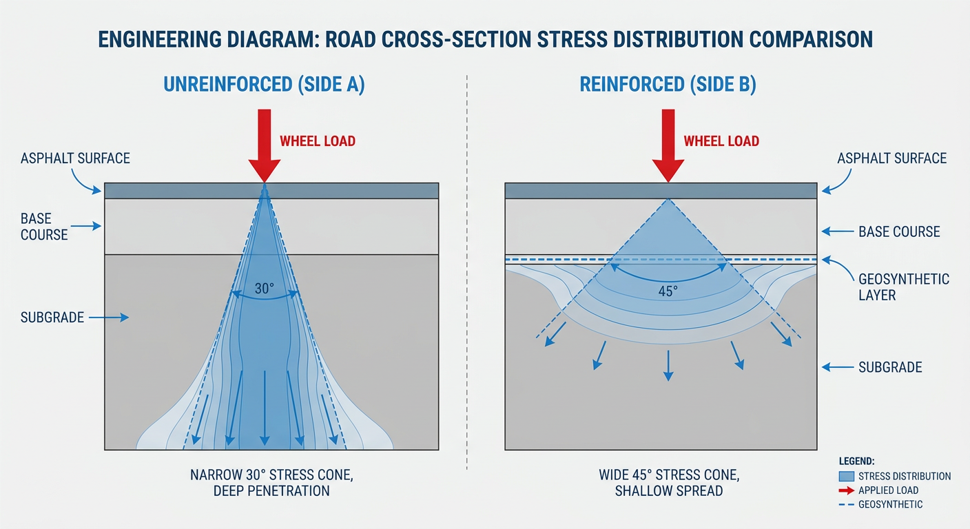
Comparison of vertical stress distribution between unreinforced aggregate and geosynthetic reinforced sections.
The practical implication is straightforward: to reduce subgrade stress to acceptable levels, you need sufficient aggregate thickness. For a 20,000-pound single-axle load (H-20 classification per FHWA standards) on a subgrade with a CBR of 3, unreinforced aggregate design typically requires 18–24 inches of well-graded base course. On extremely weak subgrades (CBR below 2), this can exceed 30 inches.
The Real-World Cost Problem
Thick aggregate sections create cascading project costs that extend far beyond material price per ton:
- Excavation depth — deeper sections require more cut, more spoil disposal, and potentially groundwater management
- Trucking volume — aggregate is heavy (approximately 1.4 tons per cubic yard), and hauling costs often exceed material costs on remote sites
- Compaction time — thick lifts require multiple passes with heavy compaction equipment, extending installation timelines
- Environmental footprint — more aggregate means more quarry extraction, more fuel consumption, and higher embodied carbon
For industrial applications—energy access roads, oil and gas lease roads, mining haul roads—these costs compound across miles of unpaved road construction. A 10-mile lease road at 24 inches of aggregate versus 10 inches represents thousands of additional truck trips and weeks of additional installation time.
Subgrade Variability Compounds the Problem
Field conditions rarely match laboratory assumptions. Subgrade CBR values can vary significantly across a single project site due to soil type transitions, moisture content changes, and organic layer depths. Designing to the weakest soil condition means over-building across the entire alignment—wasting material on sections where the subgrade could support a thinner section.
Conventional approaches address variability by either accepting the over-design cost or conducting extensive geotechnical investigation to map soil conditions and design variable sections. Both approaches add cost. Geosynthetic reinforcement offers a third path: provide consistent structural improvement across the entire alignment, allowing engineers to design to a standard reinforced section that performs on variable subgrades.
How Geosynthetic Reinforcement Solves Unpaved Road Failures
Geosynthetics improve unpaved road performance through three distinct mechanisms, each contributing differently depending on the geosynthetic type, loading conditions, and subgrade characteristics. Understanding these mechanisms is essential for selecting the right reinforcement approach for your project requirements.
Mechanism 1: Improved Load Dispersion Angle
All geosynthetics improve the effective load dispersion angle through the aggregate layer. Instead of the 26.5° to 30° angle in unreinforced aggregate, reinforced sections can achieve effective angles of 35° to 45° or higher. This wider dispersion cone spreads wheel loads across a larger subgrade area, reducing peak vertical stress proportionally.
The magnitude of improvement depends on the geosynthetic type. Geogrids provide moderate improvement through interlock between aggregate particles and grid apertures. Geocells provide the highest improvement because cellular confinement prevents lateral aggregate displacement entirely, forcing load transfer through confined compression rather than shear.
Mechanism 2: Lateral Confinement and Apparent Cohesion
Unreinforced aggregate fails under repeated loading primarily through lateral displacement. Wheel loads push aggregate particles outward, creating ruts in the wheel paths and heave at the edges. This lateral movement continues with each load cycle until the aggregate layer loses structural integrity.
Cellular confinement addresses this failure mode directly. When aggregate is placed and compacted within geocell walls, the HDPE cell structure physically prevents lateral displacement. The confined aggregate exhibits dramatically increased stiffness and apparent cohesion—behaving more like a semi-rigid plate than a loose granular layer.
BaseCore HD™ Geocell achieves a structural layer coefficient of 0.35 per AASHTO flexible pavement design methodology—compared to approximately 0.14 for unreinforced crushed stone. This means every inch of geocell-reinforced aggregate provides the structural equivalence of approximately 2.5 inches of unreinforced aggregate.
Mechanism 3: Beam Action and Tensioned Membrane Effect
Interconnected geocell panels create a continuous structural system that distributes concentrated loads across adjacent cells. When a wheel load is applied to one cell, the HDPE cell walls transfer stress laterally to surrounding cells through beam action. This load sharing prevents localized failure and spreads the load across a much larger effective footprint than unreinforced aggregate.
Additionally, the tensioned cell walls redistribute vertical loads as tensile forces through the panel—the membrane effect. As the loaded cell deforms slightly under pressure, the surrounding cell walls develop tension that resists further deformation and adds structural capacity beyond what the aggregate infill alone provides.
The U.S. Army Corps of Engineers documented these mechanisms in technical reports dating to the 1970s, establishing geocell technology as a proven approach for rapid construction of roads and working platforms on weak soils. USACE research demonstrated that geocell-reinforced sand could support military vehicle traffic on subgrades where unreinforced sand would fail immediately.
BaseCore’s engineering team provides free project evaluations for unpaved road construction. We’ll analyze your subgrade conditions, loading requirements, and project constraints to recommend the optimal geocell depth and infill specification. Request a quote at basecore.co or call 888-511-1553.
Geosynthetic Types Compared: Geotextiles, Geogrids, and Geocells
The term “geosynthetic reinforcement” encompasses three fundamentally different product categories, each providing distinct mechanisms and performance levels for unpaved road applications. Selecting the appropriate type—or combination—requires matching product capabilities to project-specific loading, subgrade conditions, and performance requirements.
Geotextiles: Separation and Filtration
Geotextile fabrics serve primarily as separation and filtration layers rather than structural reinforcement. Placed between the subgrade and aggregate base, geotextiles prevent fine-grained subgrade soils from migrating upward into the aggregate under repeated loading (a failure mode called “pumping”) and prevent aggregate from being pushed down into soft subgrades.
While geotextiles provide some tensioned membrane effect under load, their primary contribution is maintaining aggregate layer integrity over time rather than reducing required aggregate thickness. On very weak subgrades (CBR below 3), geotextile separation is often essential regardless of other reinforcement methods used.
Best application: Subgrade separation on fine-grained or saturated soils, filtration in drainage applications, and as an underlayment beneath geocell or geogrid reinforcement systems.
Geogrids: Aggregate Interlock Reinforcement
Geogrids provide reinforcement through mechanical interlock between aggregate particles and grid apertures. When aggregate is compacted onto a geogrid layer, particles lock into the grid openings, creating a composite layer with improved lateral restraint and load distribution compared to unreinforced aggregate.
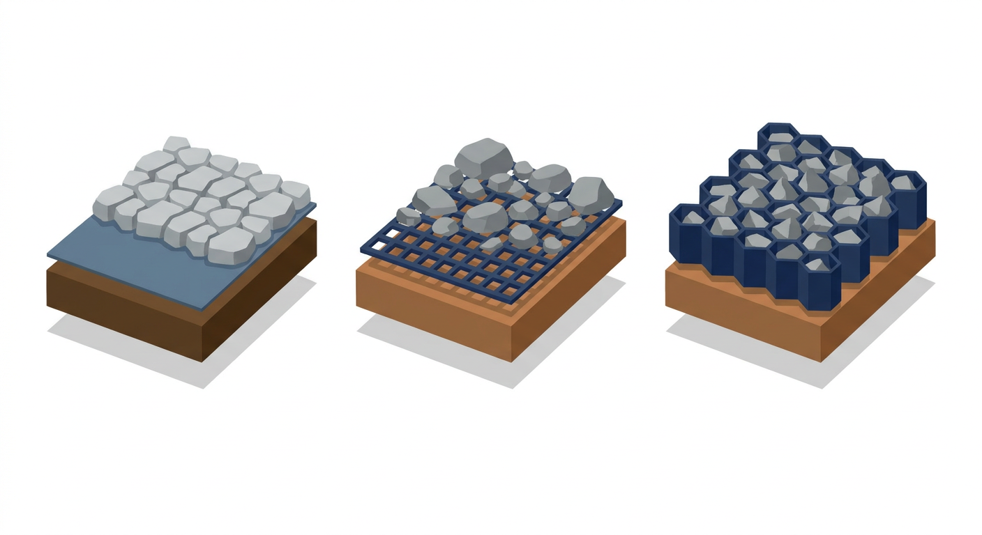
Functional comparison of Geotextiles (separation), Geogrids (interlock), and Geocells (confinement).
Geogrids typically allow 20–30% aggregate thickness reduction compared to unreinforced sections on equivalent subgrades. They’re most effective with angular, well-graded aggregate that interlocks effectively with the grid apertures. Performance decreases with rounded aggregate or fine gradations that don’t engage the grid structure.
Best application: Moderate load applications on fair subgrades (CBR 3–6), permanent roads with controlled traffic, and as a supplementary reinforcement layer beneath geocells on extremely weak subgrades.
Geocells: Cellular Confinement Systems
Geocells provide the highest level of structural reinforcement through three-dimensional cellular confinement. Unlike planar geosynthetics (geotextiles and geogrids), geocells create a volumetric reinforced zone where aggregate is fully contained within interconnected HDPE cell walls.
This confinement produces dramatically higher structural performance. BaseCore HD™ Geocell achieves aggregate thickness reductions of 40–60% compared to unreinforced sections while supporting H-20 and higher load classifications. The structural layer coefficient of 0.35 per AASHTO methodology reflects this performance advantage quantitatively.
Geocells are particularly advantageous for:
- Heavy axle loads — H-20 and above (oil and gas equipment, mining vehicles, crane access)
- Weak subgrades — CBR below 3 where other geosynthetics provide insufficient reinforcement
- Variable subgrades — consistent performance across changing soil conditions
- Temporary applications — removable and redeployable for construction access and energy projects
Best application: Heavy-duty unpaved roads, temporary access roads, haul roads, lease roads, crane pads, and any application where maximum aggregate reduction and structural performance are required.
Engineering Design Methodology for Geosynthetic Reinforced Unpaved Roads
Specifying geosynthetic reinforcement for unpaved roads requires systematic evaluation of site conditions, loading requirements, and performance objectives. The following methodology provides a framework for design decisions that balances structural performance with project economics.
Step 1: Characterize Subgrade Conditions
Accurate subgrade characterization is the foundation of reinforced unpaved road design. The California Bearing Ratio (CBR) remains the most common subgrade strength parameter for unpaved road design, though other measures (resilient modulus, cone penetration resistance) may be specified for certain applications.
Key considerations for subgrade evaluation:
- CBR testing — laboratory or field CBR values should represent worst-case (saturated or seasonal high-moisture) conditions
- Variability mapping — identify transitions between soil types and moisture conditions along the alignment
- Depth to bearing stratum — determine if competent soil exists within practical excavation depth
- Drainage conditions — assess groundwater levels and surface drainage that affect subgrade strength
For preliminary design, USDA soil survey data and boring logs can provide initial CBR estimates. Final design should be based on project-specific geotechnical investigation per ASTM standards.
Step 2: Define Loading Requirements
Unpaved road loading varies dramatically by application. Establishing clear load classification early in design prevents both under-design failures and over-design waste.
Common load classifications for unpaved roads:
- H-10 — 20,000 lb gross vehicle weight, light equipment and service vehicles
- H-20 — 40,000 lb gross vehicle weight, standard highway trucks and moderate equipment
- HS-20 — tandem axle configuration, 72,000 lb gross vehicle weight
- Heavy industrial — mining haul trucks, drilling rigs, heavy cranes (often exceeding 100,000 lb)
Beyond static load classification, consider traffic volume (passes per day), speed, and whether loads are uniformly distributed or concentrated (e.g., tracked vs. wheeled equipment). Slow-moving, repetitive loads create higher accumulated stress than occasional high-speed passes.
Step 3: Select Geosynthetic Type and Depth
Match geosynthetic selection to the intersection of subgrade CBR and load requirements:
- CBR > 6, light loads — geotextile separation may be sufficient; geogrid optional
- CBR 3–6, moderate loads (H-10 to H-20) — geogrid reinforcement with geotextile separation
- CBR < 3, any load — geocell reinforcement required for meaningful aggregate reduction
- Any CBR, heavy loads (H-20+) — geocell reinforcement recommended for structural performance and material optimization
For geocell applications, cell depth selection follows structural design principles. BaseCore HD™ Geocell provides H-20 performance at 4–6 inch cell depths with appropriate aggregate infill on subgrades with CBR of 3 or higher. For lower CBR values or heavier loads, increased cell depth or supplementary geogrid reinforcement below the geocell layer may be specified.
Step 4: Specify Infill Material
Geocell performance depends significantly on infill material selection. Well-graded angular aggregate provides the highest confined strength and load-bearing capacity. Recommended infill specifications:
- Gradation — well-graded crushed stone meeting local DOT base course specifications
- Maximum particle size — typically limited to 2/3 of cell depth for proper compaction
- Angularity — angular to sub-angular particles preferred; avoid rounded river gravel
- Compaction — 95% modified Proctor density or as specified
For specific applications, alternative infill materials may be appropriate. Sand, recycite stone, or stabilized soil can be used where aggregate is unavailable or cost-prohibitive, though load-bearing capacity may be reduced. BaseCore’s engineering team provides project-specific infill recommendations based on available materials and performance requirements.
Step 5: Address Drainage and Ancillary Systems
Even properly reinforced unpaved roads fail prematurely if drainage is inadequate. Water infiltration weakens subgrade soils, reduces aggregate stiffness, and accelerates structural deterioration. Design should include:
- Surface crown or cross-slope — minimum 2% grade to drain surface water laterally
- Side ditches — adequate capacity for design storm events
- Subsurface drainage — perforated pipe or drainage aggregate where groundwater is present
- Culverts and cross-drains — at low points and drainage crossings
Geocell’s permeable structure provides an advantage in drainage design. Unlike impervious concrete or asphalt, geocell-reinforced aggregate allows vertical infiltration where appropriate for site conditions, potentially reducing surface drainage infrastructure requirements.
What Geosynthetic Type Provides the Best Reinforcement for Heavy Vehicle Traffic?
Geocells provide the best structural reinforcement for heavy vehicle traffic on unpaved roads. The three-dimensional cellular confinement prevents lateral aggregate displacement under concentrated wheel loads, maintains structural integrity across thousands of load cycles, and achieves a structural layer coefficient (0.35 for BaseCore HD™) more than double that of unreinforced aggregate.
For H-20 and heavier loads—including oil and gas equipment, mining haul trucks, and heavy construction vehicles—BaseCore HD™ Geocell delivers consistent performance where planar geosynthetics (geogrids and geotextiles) cannot provide adequate aggregate reduction. This makes geocell the preferred choice for road construction in energy, mining, and heavy industrial applications.
How Much Aggregate Can Geosynthetic Reinforcement Eliminate?
Geocell reinforcement typically reduces aggregate base thickness by 40–60% compared to unreinforced sections on equivalent subgrades. The exact reduction depends on subgrade CBR, loading requirements, and geocell depth, but this range represents documented performance across thousands of installations.
For example, an unreinforced design requiring 20 inches of aggregate base on a CBR 3 subgrade for H-20 loading could typically be reduced to 8–12 inches with properly specified geocell reinforcement. This reduction translates directly to lower material costs, reduced trucking, faster installation, and decreased environmental impact. BaseCore case studies document these aggregate reductions across diverse project types and site conditions.
What CBR Values Require Geosynthetic Reinforcement for Unpaved Roads?
Geosynthetic reinforcement becomes increasingly important as subgrade CBR drops below 6, and is typically essential below CBR 3. At CBR 3 and below, unreinforced aggregate sections become prohibitively thick (often 24+ inches for H-20 loading), making reinforcement economically necessary rather than optional.
However, CBR threshold alone doesn’t determine reinforcement necessity. Loading magnitude, traffic volume, and project constraints also drive the decision. Even on fair subgrades (CBR 4–6), geocell reinforcement may be specified to reduce aggregate costs, accelerate installation, or provide a removable temporary road. Contact BaseCore’s engineering team for project-specific recommendations based on your subgrade data.
Conclusion: Engineering Optimized Unpaved Road Performance
Geosynthetic reinforcement transforms unpaved road design from a brute-force aggregate depth calculation into an engineered optimization problem. By understanding the load distribution mechanisms—improved dispersion angle, lateral confinement, beam action, and membrane effect—engineers can specify reinforced sections that deliver equivalent or superior performance at 40–60% reduced aggregate thickness.
For heavy-duty applications demanding maximum structural performance and material efficiency, BaseCore HD™ Geocell provides the highest reinforcement factor available in geosynthetic technology, backed by 75+ year HDPE lifespan and proven performance across energy, oil and gas, mining, and infrastructure projects worldwide.
Request a free project evaluation from BaseCore’s engineering team. We’ll analyze your subgrade conditions, loading requirements, and project constraints to recommend the optimal geosynthetic reinforcement system for your unpaved road application. Get a free quote at basecore.co or call 888-511-1553.
Frequently Asked Questions
How long does geocell-reinforced unpaved road installation take compared to conventional aggregate base?
Geocell installation typically reduces construction time by 50–70% compared to equivalent unreinforced aggregate sections. The reduced aggregate volume means fewer truck loads, less compaction time, and no curing delays. A road section that would require multiple days with conventional methods can often be completed in hours with geocell reinforcement.
Can geocell reinforcement be used on saturated or high-water-table sites?
Yes. Geocell systems are permeable and drain freely, making them well-suited for sites with high groundwater or seasonal saturation. The HDPE cell walls are unaffected by water exposure, and the permeable structure prevents the hydrostatic pressure buildup that damages impervious pavements. Proper subdrainage design remains essential for long-term performance.
What is the cost difference between geocell reinforcement and unreinforced thick aggregate sections?
Total installed cost for geocell-reinforced sections is typically lower than equivalent unreinforced designs due to 40–60% aggregate reduction, fewer truck trips, and faster installation labor. Exact savings depend on site-specific factors including aggregate costs, haul distances, and subgrade conditions. Request a project evaluation for detailed cost analysis.
Are geocell systems approved for DOT and government projects?
Geocell technology has been used on DOT, military, and government projects for decades, with documented applications by the U.S. Army Corps of Engineers dating to the 1970s. Specific approval requirements vary by agency and jurisdiction. BaseCore provides technical documentation and engineering support for specification development on government projects.
Can geocell reinforced roads be removed and reinstalled for temporary applications?
Yes. Unlike concrete or asphalt, geocell systems can be excavated, cleaned, and redeployed for temporary access road applications. This makes geocell particularly valuable for construction access, energy project roads, and other applications where the road will be removed after project completion. The BaseCore™ Geocell 75+ year lifespan supports multiple deployment cycles.
This article is for informational purposes only and does not constitute engineering advice. The technical information provided reflects published geotechnical principles, industry standards, and BaseCore’s product documentation. Site conditions, loading requirements, environmental factors, and regulatory requirements vary by project—consult BaseCore’s engineering team or a licensed professional engineer for project-specific design recommendations. For current product specifications, project evaluations, and pricing, visit basecore.co or call 888-511-1553.